
Compared to ordinary LCDs, TFT LCDs offer very sharp and crisp pictures/text with shorter response times. TFT LCD displays are being used in more and more applications, giving products better visual presentation.
Structure of TFT LCD
TFT is an abbreviation for “Thin Film Transistor.” The color TFT LCD display has transistors made up of thin films of Amorphous silicon deposited on a glass substrate. It serves as a control valve to provide an appropriate voltage onto liquid crystals for individual sub-pixels. That’s why a TFT LCD display is also called an Active Matrix display.
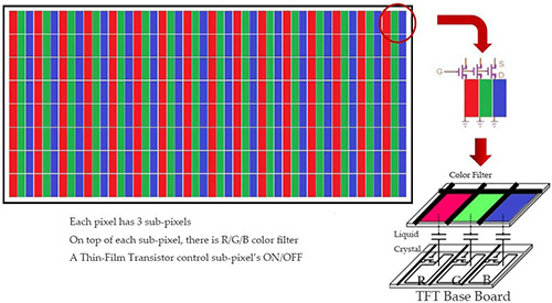
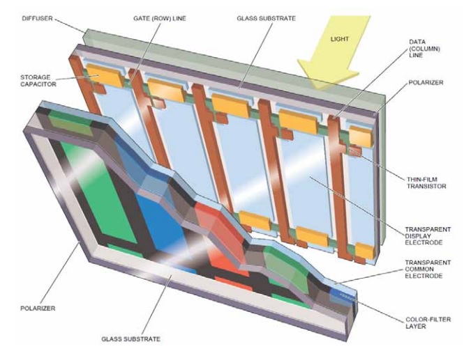
A TFT LCD has a liquid crystal layer sandwiched between a glass substrate formed with TFTs and transparent pixel electrodes, and another glass substrate with a color filter (RGB) and transparent counter electrodes. Each pixel in an active matrix is paired with a transistor that includes a capacitor, which gives each sub-pixel the ability to retain its charge instead of requiring an electrical charge sent each time it needs to be changed. This means that TFT LCD displays are more responsive.
TFT LCD Driving Principle
To understand how a TFT LCD works, we first need to grasp the concept of a field-effect transistor (FET). A FET is a type of transistor that uses an electric field to control the flow of electrical current. It is a component with three terminals: source, gate, and drain. FETs control the flow of current by applying a voltage to the gate, which in turn alters the conductivity between the drain and source.
Using FETs, we can build a circuit as shown below. The Data Bus sends a signal to the FET Source, and when the SEL SIGNAL applies voltage to the Gate, a driving voltage is then created on the TFT LCD panel. A sub-pixel will be lit up. A TFT LCD display contains thousands or millions of such driving circuits.