
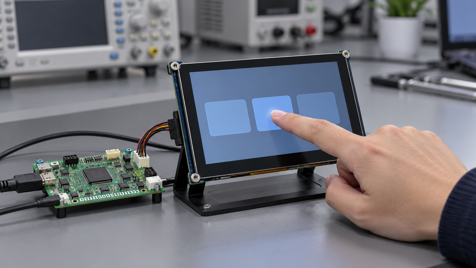
A touch display works correctly on the development bench. After installation in the equipment enclosure, buttons activate without a finger on the glass. In another prototype, a continuous drag breaks into separate touches when the power adapter is connected. The LCD image remains stable in both cases.
These symptoms do not justify replacing the touch panel immediately. They call for a controlled comparison of the sensor, touch controller, host connection, display activity, power system, and final assembly.
The first task is to find where the unwanted input appears. A false contact reported by the touch controller requires a different investigation from a correct contact mapped to the wrong screen location. This guide helps OEM hardware and HMI teams separate those faults, locate repeatable triggers, and prepare useful evidence for engineering review.
1. Why Touch Works on the Bench but Fails in the Enclosure
The bench prototype and assembled product are different test configurations. During assembly, a team may change the power adapter, cable route, cover lens, mounting pressure, nearby metalwork, and peripheral load. If several changes occur together, the first failed test cannot identify which change matters.
Infineon’s industrial touchscreen design guidance identifies nearby electronics, cable routing, and grounding of the controller and surrounding metalwork as integration factors that can affect touch performance.[1] That supports reviewing the complete assembly, rather than treating a passing loose-panel demonstration as final validation.
Create a configuration record before troubleshooting. Include the LCD and touch module models, controller identity, firmware and configuration versions, host board revision, power source, cable layout, and cover stack. Photograph the working bench setup and the failing enclosure setup.
Then restore the working baseline and introduce changes one at a time where practical. A comparison that can be repeated in both directions is especially useful: the fault appears when one condition is introduced and disappears when that condition is removed.
This identifies an association, not necessarily the coupling mechanism. An adapter change, for example, may alter several electrical conditions at once. Keep the conclusion as specific as the evidence allows.
2. Separate Ghost Touch, Coordinate Errors, and Lost Input
“Touch is unstable” is too broad for a diagnostic report. Begin with a description of what the user sees and what the input system reports.
| Symptom | Useful distinction | First evidence to collect |
|---|---|---|
| Ghost touch | Contacts appear with no intended physical contact. | Timestamped contact reports during an untouched test interval. |
| Fixed coordinate offset or rotation | Each real contact produces a consistent but incorrect location. | Touch positions at known targets and the host’s coordinate transformation. |
| Jitter or broken drag | A steady finger produces moving coordinates or repeated contact release. | Contact IDs, coordinates, and continuity during a repeatable gesture. |
| Missed touch | A deliberate contact does not reach the application. | Controller reports, host events, and application response for the same attempt. |
| Device disconnect or reset | The host loses the touch device or it restarts. | Bus, driver, and power logs, including recovery behavior. |
Use three observation levels where available: controller diagnostics, operating-system input events, and application behavior. Sensor acquisition data from a vendor diagnostic tool are not the same as operating-system “raw input” events. The latter have already passed through controller processing and the host driver.
Android’s touch-device documentation describes device-specific configuration and orientation handling. A consistent rotation or scaling error should therefore prompt a mapping review before changes to sensor sensitivity.[2]
On a suitable Android engineering build, the getevent tool can show input capabilities and live events. Its labeled, timestamped output can help correlate reported contacts with a test trigger.[3]
getevent -lp
getevent -lt /dev/input/eventX
Run these through the engineering shell with the required permissions. Identify the actual touchscreen event node; eventX is a placeholder, not a fixed device name. Record a short no-touch interval, followed by a known gesture. If the application activates a button without a corresponding touch event, investigate its event handling and other input sources.
If false contacts do appear at the host input layer, continue upstream. That observation does not distinguish sensor noise from controller, driver, or reporting faults by itself.
3. Identify Noise from the Display and Power System
Capacitive touch sensing detects changes in electrical coupling at the sensor. Display and power circuitry can interfere with that process. Microchip’s mXT640U documentation explicitly discusses charger noise and display-noise suppression, showing that these are recognized controller design concerns.[4]
Use this as a reason to test likely sources, not as proof that a particular source caused the fault. A stable LCD image does not establish that its electrical activity is harmless to the adjacent touch system.
Separate brightness from image activity
Run a fixed image at several intended brightness settings. Then hold brightness constant and compare static content with representative screen updates. Record the reported contacts and any available controller noise indicators.
If a fault follows brightness changes, review the backlight driver and its control behavior alongside touch data. If it follows screen updates, investigate the display-related path. Neither comparison alone proves that PWM or a particular display signal is responsible.
Keep the rest of the configuration fixed, including supply, cable arrangement, touch firmware, and enclosure state. Document whether “screen off” means a black image, backlight off, or a powered-down display. These conditions are not interchangeable.
Compare approved power configurations
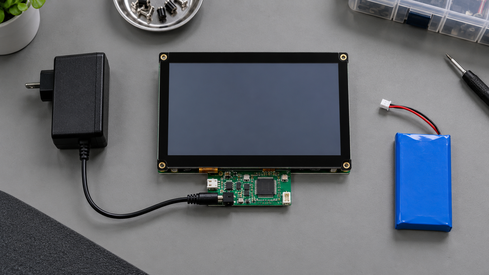
Where the product supports both battery and adapter operation, compare those modes under the same workload. Otherwise, compare suitable approved supplies while preserving voltage, current capability, and required electrical protection. Record whether faults occur continuously or only during connection and load transitions.
A supply comparison can help narrow the trigger. Follow it with measurements appropriate to the design, including the touch-controller supply and relevant reference points. Supply voltage measured at a distant connector does not describe every condition at the controller.
Introduce peripheral activity deliberately
Test representative loads separately: a relay transition, motor activity, radio transmission, or another subsystem used in the product. Mark the time of each action in the record. Compare repeated active and inactive intervals.
Do not disconnect protective earth or bypass required isolation to make a touch fault disappear. Such a result would change the product’s electrical protection and would not establish a valid production solution.
4. Review Grounding, Cable Routing, and Mechanical Integration
If the fault appears only after assembly, avoid changing controller thresholds first. Preserve the failed configuration and inspect what the assembly changed.
Document the reference and return paths
Use the schematics and controller integration instructions to identify signal ground, chassis connections, shields, and protective earth where present. Record how each connects in the actual prototype. Treat them as separate design responsibilities.
A grounded bench instrument or connected laptop can also change the test arrangement. Record attached equipment when a measurement or diagnostic connection changes the symptom. Otherwise, a team may unknowingly compare two different electrical configurations.
A temporary change should have a defined purpose and a documented connection. If it improves the symptom, confirm that the proposed production implementation is compatible with the product’s electrical architecture. “Add more ground” is not a complete design instruction.
Compare cable routes without changing everything else
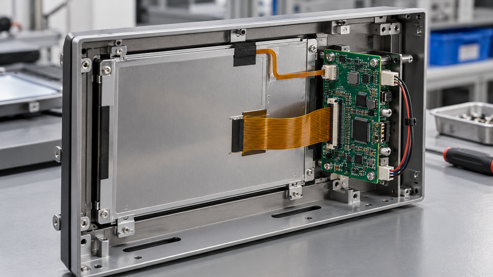
Photograph the touch FPC or cable next to the display cable, power wiring, and switching components. Where the assembly permits, test a controlled alternative route using the same cable and connectors. Avoid simultaneously changing cable length, shielding, and firmware.
If the alternative route helps, repeat the original route to verify the association. Retain the physical arrangement in the report, including connector seating and mounting. A test that cannot be reconstructed is difficult to use during supplier review.
Check the production cover and mounting
Inspect the installed cover lens, adhesive or bonding layers, clearances, supports, and fasteners against the approved assembly design. Check whether assembly introduces visible distortion, unintended contact, or connector strain.
Separate mechanical and electrical changes where possible. For example, compare the cover installed before enclosure electronics are active, then repeat with the electronics operating. This helps prevent a mounting effect from being mislabeled as electromagnetic noise.
Validate the production assembly rather than a convenient substitute. For wider selection requirements, see RJY’s TFT LCD module with touch screen guide.
5. Decide When Controller Tuning Is Appropriate
Tuning is appropriate when the controller supports the required adjustment, diagnostic evidence explains its purpose, and the team can verify the resulting trade-off. Establish that the supply, connections, sensor assembly, and host mapping are correct first.
Microchip’s mXT640U provides model-specific acquisition filtering and noise-suppression functions. Its documentation also describes compensation for some grounding-related signal degradation.[4] These examples show why controller identity matters. They do not establish that another controller or an RJY module has the same capabilities.
| Possible adjustment, where supported | Question it should answer | Behavior to retest |
|---|---|---|
| Detection threshold | Are unwanted excursions being accepted as contacts? | Intentional light touches, edges, and required gloves. |
| Filtering or debounce | Can brief unwanted reports be rejected? | Response delay, short taps, and gesture continuity. |
| Acquisition frequency or timing | Does the controller’s supported acquisition change improve measured behavior? | The complete operating range and other noise sources. |
| Baseline or recalibration settings | Is the reference state being established and maintained correctly? | Startup, idle periods, environmental changes, and sustained contact. |
| Contact suppression features | Can unwanted contact types be distinguished? | All intended gestures and simultaneous contacts. |
The table is a review framework, not a list of guaranteed controls. Ask the controller supplier which parameters are available and what each changes. Do not copy register values or thresholds from a different sensor geometry.
Keep every configuration version recoverable. Change one setting or one documented parameter group, preserve the previous file, and record the reason. Compare the result against both the original fault and normal touch tasks.
Suppressing all contacts would eliminate ghost touches while making the interface unusable. The meaningful result is correct input under the required conditions. A tuning change must preserve that result, including the operator actions most likely to be weakened by the change.
6. Build a Repeatable Touch Validation Matrix
Turn the suspected trigger into a repeatable test before expanding validation. Once a correction is proposed, use a broader matrix to check that the improvement persists and does not create another fault.
| Variable | Coverage | Record |
|---|---|---|
| Power source | Each approved adapter and supported battery mode. | Supply identity, loading, and touch result. |
| Display state | Documented off state, static UI, and representative updates. | Brightness and exact display activity. |
| Peripheral load | Required radios, actuators, and switching loads. | Activity timing and any correlated input fault. |
| Assembly | Working baseline and intended production enclosure. | Cover, mounting, cable route, and configuration changes. |
| Operator action | No-touch interval, taps, holds, edge targets, drags, and required gestures. | False reports, missed actions, coordinate behavior, and continuity. |
| Use conditions | Required gloves, approved cleaning conditions, and specified environmental states. | Exact conditions and acceptance result. |
| State transitions | Startup, permitted supply changes, idle recovery, and supported sleep/wake. | Fault occurrence and recovery behavior. |
Define acceptance criteria before testing. Specify the observation interval for unintended contacts, number of intentional actions, allowed coordinate error, and response requirements. Choose these from the product workflow; do not invent a universal standard.
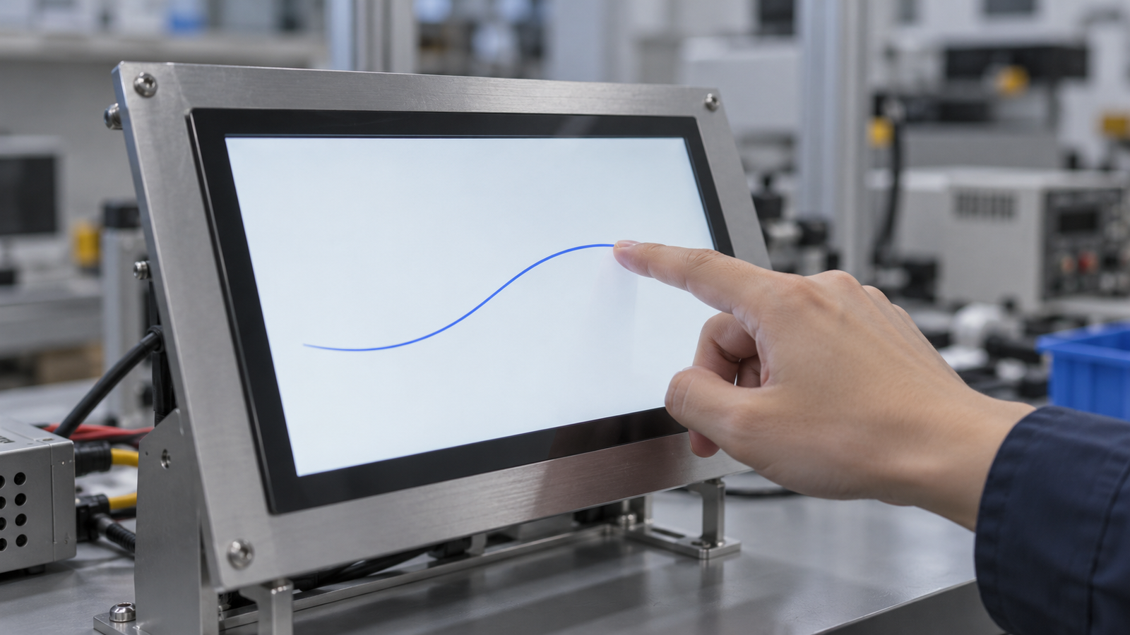
Retain both counts and context. “Two missed taps during the defined edge-target test” is more informative than “touch mostly works.” Likewise, report the number of trials and conditions when no failures occur. A clean run establishes what happened in that run, not zero risk under all conditions.
Glove and wet-surface requirements need explicit project validation. Their inclusion in a matrix does not imply that every capacitive touchscreen supports them. Use RJY’s Android touch and HDMI touch integration guide when host input routing and separate video/touch connections also need review.
7. Prepare Evidence for a Supplier Engineering Review
A supplier needs a reproducible fault and a known configuration. Provide the touch controller and firmware identity, LCD model, host revision, operating-system build, power source, assembly photos, and exact reproduction steps.
Attach synchronized evidence where available: a screen recording, input-event capture, controller diagnostic export, and relevant power measurements. Identify what each file represents. A processed contact log cannot be presented as a sensor acquisition trace.
Illustrative report format, not an RJY test result: With the assembled HMI untouched, unintended contact reports appear during the defined adapter-powered test. The same software and cable layout are used for the baseline comparison. Attach trial counts, event timestamps, supply details, controller configuration, and photographs. State whether the fault returns when the original condition is restored.
Include changes that did not help. This prevents repeated work and makes it easier to judge whether a proposed tuning change addresses the observed mechanism. Describe temporary improvements without claiming a confirmed root cause.
Agree on the next test and its expected evidence. That is a stronger engineering handoff than asking for an unspecified “more sensitive” or “more noise-resistant” panel.
8. FAQ
Does ghost touch always mean that the touch panel is defective?
No. Unintended contacts can involve sensing interference, controller configuration, assembly, or reporting faults. Compare controller diagnostics, host input events, and application behavior before deciding which component needs replacement.
Why can a touchscreen work on battery but fail with an adapter?
The adapter-powered configuration can change noise and electrical coupling conditions. A repeatable comparison identifies a useful trigger, but measurements are still needed to establish the mechanism and a valid correction.
Is a fixed touch-coordinate offset usually a noise problem?
A consistent offset, scaling error, or rotation should first prompt a review of coordinate mapping and display association. Check reported positions against known targets before changing sensor settings.
Can stronger filtering remove ghost touches without any trade-off?
Not necessarily. Depending on the controller and settings, filtering can affect response time or intended gestures. Validate short taps, continuous drags, edge operation, and all required input conditions after tuning.
Should every capacitive touchscreen use the same grounding and tuning settings?
No. The correct design depends on the sensor, controller, cover stack, enclosure, power system, and host. Use the applicable integration instructions and validate the complete product configuration.
Discuss Your Embedded Touch Display with RJY
RJY Display supports customization based on existing display modules, including touch, cover glass, controller-board, firmware, and mechanical coordination according to project feasibility. Submit your touch-display integration requirements with the module details, enclosure information, operating conditions, and reproducible fault evidence. Specific controller features and adaptation scope require confirmation for the project.
References
Manufacturer sources describe the identified products or design guidance; they do not establish equivalent features in RJY modules. Diagnostic procedures and test matrices above are proposed engineering methods, not reported product test results.