

A display reaches end of life, but the equipment built around it may still have years of market demand. This is a familiar problem for manufacturers of industrial controls, smart-home products, security terminals, instruments and specialized electronic equipment.
Finding a discontinued LCD replacement is rarely as simple as ordering another screen with the same diagonal size. Two TFT LCD modules can appear similar while differing in mechanical outline, active area, interface, pin definition, timing, backlight circuit, touch controller or initialization requirements.
The objective is therefore not merely to find a screen that can display an image. It is to identify the lowest-risk replacement path while preserving as much of the existing enclosure, electronics, firmware and production process as practical.
Why a Discontinued Display Can Threaten an Entire Product Platform
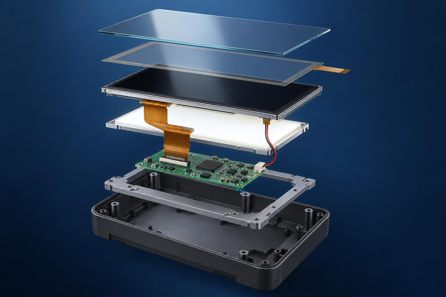
The LCD is physically and electrically connected to several parts of a finished product. Its dimensions affect the enclosure and mounting structure. Its signal interface affects the host board. Its backlight affects the power circuit. Its touch panel may depend on a particular controller and firmware configuration.
When the original module becomes unavailable, the consequences can extend beyond purchasing:
- Production may stop even when every other component remains available.
- Service teams may be unable to repair installed equipment.
- A rushed substitute may require unexpected firmware or PCB changes.
- A different active area may no longer align with the enclosure window.
- Brightness, color or viewing behavior may change between production batches.
- Touch behavior may differ even when the replacement looks mechanically similar.
This is why an LCD end-of-life project should be treated as a controlled engineering change, not only as a sourcing exercise.
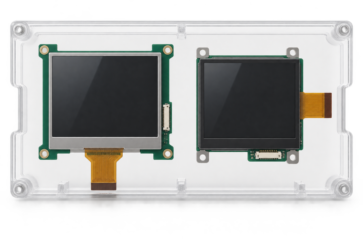
Three Different Meanings of “Replacement LCD”
Before searching for alternatives, define what level of replacement the project actually requires.
Exact replacement
An exact replacement is the same approved model or an officially documented continuation of it. This route normally creates the least engineering work, but availability may be limited and future supply still needs to be confirmed.
Form-fit-function alternative
A form-fit-function alternative is a different module intended to perform the same role with minimal product changes. It must be evaluated across mechanical, electrical, optical and software requirements. Matching diagonal size and resolution alone does not establish compatibility.
Adapted replacement assembly
If a direct equivalent is unavailable, an existing TFT module may be adapted with a customized FPC, cover glass, touch panel, backlight solution, mounting structure or controller board. This approach can sometimes preserve the enclosure or host platform even though the internal display assembly changes.
The best route depends on product lifetime, remaining demand, regulatory obligations, engineering resources and the cost of changing surrounding components.
The Seven Compatibility Layers That Must Be Checked
1. Mechanical outline and active area
Start with the complete mechanical drawing rather than the nominal screen size. Compare module width, height, thickness, active area, viewing area, bezel, mounting features and component protrusions.
The new active area must align with the product window. Even a small positional difference can expose the metal frame, hide pixels or interfere with printed cover-glass borders. Thickness changes may affect seals, brackets, screw pressure and internal clearances.
FPC position and bending direction are equally important. A connector moved from one edge to another may collide with the housing or require an impractical cable fold.
2. Display interface
Confirm whether the original module uses RGB, LVDS, MIPI DSI, SPI, MCU or another interface. The replacement must be compatible with the host signal or supported through a properly evaluated controller solution.
An interface name is only the beginning. Lane count, color depth, signal mapping, voltage levels, clock requirements and timing must also be reviewed. A board designed for one MIPI or LVDS configuration should not be assumed to support every panel using the same interface family.
3. Resolution and timing
Matching resolution can reduce software and UI changes, but it does not guarantee matching timing. Review pixel clock, horizontal and vertical synchronization, porch values, refresh requirements and polarity where applicable.
If the host system generates fixed timing, the candidate LCD must accept it or the controller and firmware must be adjusted. A replacement that produces an image on a laboratory bench may still show instability, intermittent startup or edge artifacts if timing margins are poor.
4. Connector and pin definition
A matching connector does not mean a matching pinout. Two modules can use connectors with the same pitch and pin count while assigning power, ground, data, reset and backlight functions differently.
Connecting them without checking the datasheets can prevent operation and may damage the LCD or host electronics. Compare every pin, its direction, voltage and startup requirement. If the definitions differ, a custom FPC or adapter board may be considered after electrical review.
5. Backlight system
The LCD image and LED backlight are separate parts of the system. Compare LED configuration, forward-voltage range, operating current, connector definition, brightness-control method and driver topology.
The existing backlight driver may not be suitable for a replacement string arrangement. Excessive current can shorten backlight life, while insufficient voltage or current can cause low brightness or unstable operation. PWM behavior should also be checked if the application uses dimming.
6. Touchscreen integration
If the original product includes touch, review the complete touch assembly rather than the LCD alone. Important factors include:
- Touch technology and number of required touch points
- Touch-controller model and communication interface
- Cover-glass thickness, shape and printed border
- Bonding structure and total assembly thickness
- Touch coordinate direction and active-area alignment
- Firmware, driver and operating-system support
- Expected operation with gloves, moisture or electrical noise
A new touch controller may require driver work, parameter tuning or revised coordinate mapping. Final behavior should be verified in the assembled equipment because grounding, nearby electronics and cover-glass design can influence capacitive touch performance.
7. Optical and environmental requirements
Compare brightness, contrast, viewing direction, color characteristics and operating-temperature requirements against the real application. The datasheet values should be considered together with enclosure design, ambient lighting and user position.
A replacement can be electrically functional yet unsuitable because it appears inverted from the normal viewing angle, lacks visibility in the installation environment or behaves differently at the equipment’s temperature limits.
Replacement LCD Compatibility Checklist
| Requirement | What to Compare | Potential Consequence |
|---|---|---|
| モジュールが適合する場合は低い | Outline, thickness, active area, mounting and FPC position | Housing interference or incorrect window alignment |
| インターフェース | Interface type, lane or bus configuration and voltage levels | No image or host-board redesign |
| Timing | Pixel clock, synchronization and porch requirements | Unstable image, artifacts or startup failure |
| Pinout | Every connector pin and electrical function | Non-operation or component damage |
| バックライト | LED arrangement, current, voltage and dimming | Low brightness, instability or reduced lifetime |
| タッチ機能 | Controller, interface, driver, cover glass and coordinates | Incorrect or unreliable touch behavior |
| Optical performance | Brightness, viewing direction, contrast and color | Poor readability in the finished product |
| Environment | Temperature, vibration and application conditions | Field performance that differs from bench testing |
Why the Connector Cannot Determine Compatibility
Connector appearance is one of the most common shortcuts in replacement projects. It is also one of the most dangerous.
The same connector family can carry different interfaces and pin definitions. Even when the data pins correspond, the power rails, reset sequence, backlight pins or touch signals may differ. Some modules integrate additional circuitry that another module does not.
The correct comparison starts with the original and proposed module datasheets. When the original datasheet is unavailable, the product team should collect board schematics, connector measurements, panel markings, photographs, operating voltages and signal information before selecting a candidate.
Can a Controller Board Solve the Problem?
A controller board can be useful when the available replacement display does not directly match the existing video source. For example, an appropriate controller may convert a host output to the interface required by the selected LCD.
However, a controller board is not a universal adapter. Compatibility depends on the exact LCD panel, resolution, interface, pin definition, timing, backlight, touch path and firmware. The board must also fit the available space and satisfy the product’s power, startup and environmental requirements.
Before selecting a board, prepare the panel datasheet and system information described in RJY’s HDMI-to-MIPI controller-board compatibility guide. For Android-based equipment, the TFT LCD and Android controller-board matching guide explains why panel and host information must be reviewed together.
How to Preserve the Existing Enclosure
Replacing the enclosure tooling may cost more than adapting the display assembly. Several approaches can help preserve the existing product exterior when a mechanically identical LCD is unavailable.
Use the cover glass as a mechanical interface
A customized cover glass can retain the original outer dimensions and printed viewing window while being designed around a different LCD active area. This is most practical when the new module is smaller or can be positioned correctly behind the existing opening.
Add an internal mounting frame
A revised bracket or adapter frame can locate the new module without changing the exterior enclosure. The design must avoid concentrated pressure on the LCD and provide appropriate clearance for the FPC, components and cables.
Customize the FPC or cable route
When signal definitions and electrical requirements allow it, an adapted FPC can help connect a replacement module to the existing board or reposition the connection. This requires a complete pinout and signal-integrity review; it is not merely a mechanical extension.
Review the full stack thickness
The LCD, adhesive, touch sensor, cover glass, gasket and mounting structure form one mechanical stack. Changing one layer may alter bezel height, touch performance, optical appearance or sealing pressure. The complete assembly should therefore be modeled and prototyped before production.
Do Not Ignore Firmware and Software Dependencies
Display replacement problems are not always visible in mechanical drawings. The host software may contain panel-specific timing, initialization commands, orientation settings, gamma values or touch drivers.
Review whether the existing system:
- Initializes the panel directly through firmware
- Uses fixed display timing or dynamically reads display information
- Depends on a particular driver IC
- Assumes a fixed resolution or screen orientation
- Includes touch-controller-specific drivers
- Maps touch coordinates to a fixed active area
- Controls backlight brightness through software
If the candidate module uses a different driver IC or timing configuration, firmware changes may be required even when the electrical interface is similar.
A Practical Validation Process
Step 1: Create an original-display specification file
Collect the original datasheet, mechanical drawing, pin definition, interface timing, backlight information, touch documentation and photographs of the installed assembly. Record product-level requirements separately from the original display specifications so the team knows which features are essential and which can change.
Step 2: Compare candidate modules on paper
Build a line-by-line comparison covering all compatibility layers. Classify each item as matched, adaptable, requiring redesign or not yet confirmed. Do not order production quantities while critical fields remain unknown.
Step 3: Perform electrical bench testing
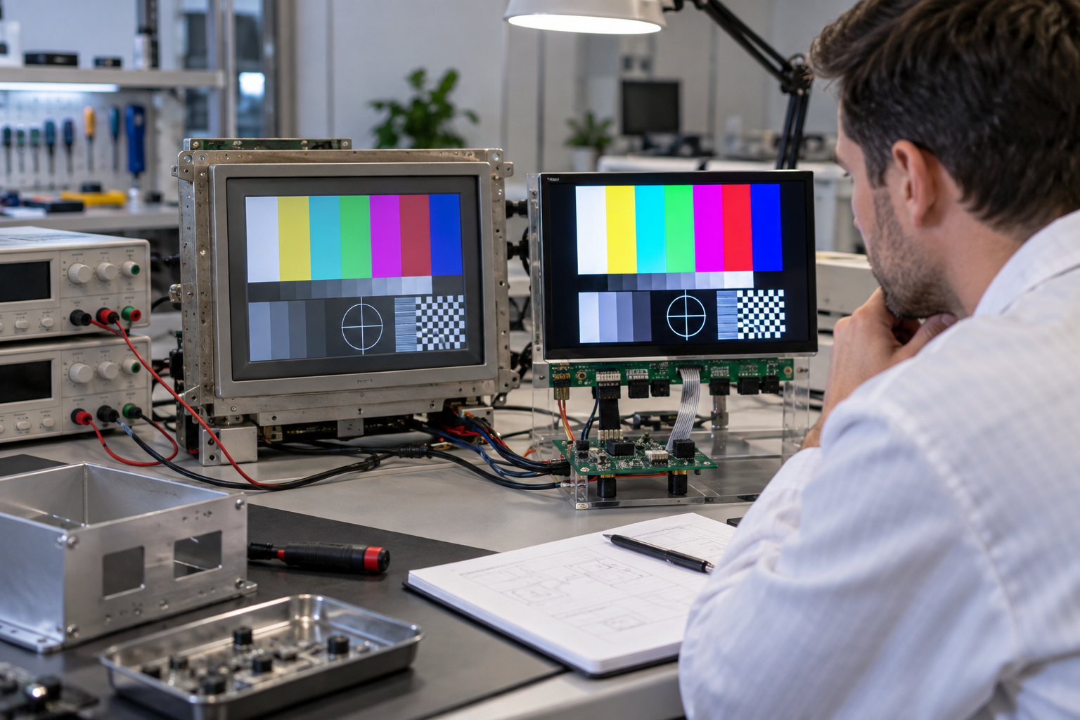
Test the candidate with the intended host or an appropriately configured development setup. Verify power sequencing, current, timing, startup, backlight control, image stability and touch communication.
Step 4: Build an enclosure prototype
Install the display, touch panel and any adapter parts in a representative enclosure. Check active-area alignment, FPC clearance, mounting pressure, viewing angles, cable strain and serviceability.
Step 5: Validate the actual application
Evaluate the assembly under the product’s expected operating conditions. Testing may include temperature, ambient light, repeated startup, touch behavior, electrical noise and relevant mechanical stresses, depending on the application.
Step 6: Run a controlled pilot build
A pilot build can reveal assembly variation and production-process issues that a single engineering sample may not show. Document the approved module, firmware, cables, adhesives, mounting parts and inspection criteria before moving into regular production.
Compare Total Change Cost, Not Only Display Price
A lower-priced LCD is not necessarily the lowest-cost replacement. The commercial evaluation should include:
- Display-module price and minimum order requirements
- Engineering and firmware effort
- FPC, adapter-board or controller-board development
- Cover-glass, touch and mechanical tooling
- Prototype and validation costs
- Production-line changes and documentation updates
- Inventory risk and expected remaining product demand
- Field-service and spare-part requirements
For a mature product with limited remaining demand, a controlled adapter solution may be more practical than redesigning the main PCB and enclosure. For a platform expected to continue for many years, a broader display-architecture update may provide better long-term flexibility.
Design the Next Revision for Easier Display Migration
An end-of-life event can also expose weaknesses in the original product architecture. Future revisions can reduce replacement risk by:
- Separating the display connection from the main control board
- Using replaceable interface or adapter boards where appropriate
- Maintaining complete panel and timing documentation
- Keeping firmware display parameters configurable
- Allowing reasonable mechanical tolerance around the LCD
- Controlling the exterior with a separate cover-glass design
- Qualifying a second display option before it becomes urgent
No architecture can eliminate component lifecycle risk, but these decisions can reduce the cost and time required for the next migration.
How RJY Can Support a Discontinued LCD Replacement Project
RJY Display can review a replacement project beginning with the original module and the finished equipment requirements. Depending on feasibility and project scope, support may include:
- Identifying candidate TFT LCD modules from existing platforms
- Comparing mechanical dimensions, active area and interface requirements
- Customizing cover glass and capacitive touch assemblies
- Reviewing backlight requirements and visibility targets
- Adapting FPC direction, length or connector arrangement
- Evaluating controller-board compatibility
- Coordinating display-related firmware and mechanical integration
This support does not mean every obsolete display can be replaced without system changes. The practical scope can be confirmed only after the original display, host electronics, enclosure and application requirements have been reviewed.
Information to Send for an Engineering Review
- Original LCD manufacturer and complete model number
- Original datasheet, drawing and pin definition
- Equipment photographs and enclosure drawings
- Display interface and host-processor information
- Backlight circuit or driver information
- Touchscreen and touch-controller requirements
- Required viewing direction, brightness and operating conditions
- Existing firmware or operating-system platform
- Parts of the product that cannot be changed
- Prototype quantity, estimated demand and project schedule
Replace the Display Without Losing Control of the Product
A discontinued TFT LCD does not automatically require a complete product redesign. It does require a structured comparison of the display, backlight, touch, electronics, firmware and enclosure as one system.
The earlier these dependencies are identified, the easier it is to choose between a direct substitute, an adapted assembly and a broader redesign. If your product is affected by an obsolete display, explore RJY custom display solutions または contact RJY with the original module information for an engineering review.
よくある質問
Can I replace a discontinued TFT LCD with another display of the same size and resolution?
Possibly, but size and resolution are not enough to confirm compatibility. Mechanical dimensions, active-area position, interface, pinout, timing, backlight, touch and firmware requirements must also be compared.
Does the same connector mean two LCD modules are compatible?
No. Connectors with the same appearance, pitch and pin count can use different pin definitions, voltage levels and signal configurations. The complete datasheets and electrical requirements must be checked before connection.
Can a controller board make any replacement LCD compatible?
No. A controller board must be matched to the exact panel resolution, interface, pin definition, timing, backlight and touch requirements. Firmware, host input, power and mechanical constraints must also be reviewed.
Can the original product enclosure be retained?
In some projects, the enclosure can be retained by using customized cover glass, an internal mounting frame, an adapted FPC or a revised display assembly. Feasibility depends on the original opening, internal space and candidate-module dimensions.
What information is needed to evaluate an obsolete LCD replacement?
Provide the original panel model and datasheet, mechanical drawing, pin definition, interface, backlight, touch, host-system and enclosure information, along with the operating environment and the parts of the product that cannot be changed.