Understanding TFT LCD Interface Options with STM32
Before making any connections, you need to determine your TFT LCD’s interface type. Common options include:
- Parallel (8080/6800 bus) – Requires multiple data and control lines, fast speed, ideal for larger displays.
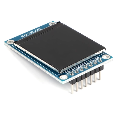
- SPIインターフェース – Fewer pins required, ideal for resource-limited projects or small displays, but slightly slower.
- RGB interface – Outputs pixel clock and RGB data lines directly, used for high-refresh applications.
Tip:
For beginners, an SPI TFT LCD is often the easiest choice because most STM32 MCUs support hardware SPI, making wiring and coding simpler.
Hardware Connections and Power Design
To drive a TFT LCD, you’ll typically need three types of power supply:
- Logic Voltage (VCC)
- Commonly 3.3V; some older modules may require 5V logic.
- Ensure the STM32 I/O voltage matches the LCD’s logic level. If not, use a level shifter (e.g., 74HC245, TXB0108).
- Backlight Power (LED+ / LED-)
- Small displays often use LED strings for backlight, requiring between 3V–12V.
- Use a constant-current driver or MOSFET with PWM control for brightness adjustment.
- GND Ground
- All grounds must be connected to avoid flickering or unstable operation.
Extra Notes:
- Add decoupling capacitors (0.1µF + 10µF) near the VCC pin for stability.
- Route the backlight power separately from logic signals to minimize noise interference.
Backlight Control – The Key to a Bright Display
Even if the logic section initializes successfully, the screen will appear blank if the backlight isn’t powered.
STM32 Backlight Control Options:
- Use a GPIO pin to drive a MOSFET on/off switch for the backlight.
- Use a timer’s PWM output to adjust brightness (recommended). A PWM frequency between 1kHz–20kHz avoids visible flicker.
Example wiring:
STM32 TIMx_CHy → MOSFET Gate → LED+ (through constant current driver or resistor)Software Initialization Process
The heart of driving a TFT LCD is sending the correct initialization commands to its controller. Let’s take the ILI9341 controller as an example.
- Hardware Reset
- Pull RESET low for at least 10ms, then pull high and wait for stabilization.
- SPI/Parallel Configuration
- For SPI, set 8-bit data mode and a clock frequency around 10–20MHz (lower if long cables are used).
- Send Initialization Commands
- Follow the controller’s datasheet sequence (pixel format, display direction, gamma settings, etc.).
- Fill the Screen
- Test with solid color fills (white, black, red, green, blue) to verify proper operation.
Basic Example Code (SPI + ILI9341)
void ILI9341_Init(void) {
    HAL_GPIO_WritePin(RESET_GPIO_Port, RESET_Pin, GPIO_PIN_RESET);
    HAL_Delay(10);
    HAL_GPIO_WritePin(RESET_GPIO_Port, RESET_Pin, GPIO_PIN_SET);
    HAL_Delay(120);

    ILI9341_SendCommand(0xEF);
    ILI9341_SendData(0x03);
    ILI9341_SendData(0x80);
    ILI9341_SendData(0x02);

    // More initialization commands...

    ILI9341_SendCommand(0x29); // Display ON
}
一般的な問題とトラブルシューティング
ディスプレイが白または黒のまま表示される
- 電源接続を確認し、バックライトが有効になっていることを確認してください。
画像のちらつきまたは歪み
- ケーブル長を短くするか、SPI/パラレルクロック速度を低下させてください。
色が正しくない
- ピクセルフォーマット設定を確認してください(RGB565 vs RGB666)。
パフォーマンス向上のためのプロのヒント
- 使用 DMA転送 描画を高速化し、CPU使用率を低下させます。
- 大型ディスプレイの場合は、RGBインターフェース用にSTM32のFSMCまたはLTDCペリフェラルの使用を検討してください。
- ノイズの多い環境では、信号線にシールドまたはEMIフィルターを追加してください。
まとめ
STM32でのTFT LCDの点灯は、ハードウェア設計とソフトウェア設定のバランスがすべてです。インターフェースタイプの理解、電圧レベルの一致、正しい初期化シーケンスに従うことで、組み込みプロジェクトに鮮やかなグラフィックを実現できます。
初心者は、小さなSPIディスプレイから始め、パラレルやRGBのようなより複雑なインターフェースへと進んでください。