The global human-machine interface (HMI) landscape in 2026 is characterized by a definitive shift toward specialized, high-resolution, and intelligent display systems. Thin-Film Transistor (TFT) Liquid Crystal Displays (LCDs) remain the bedrock of this evolution, particularly in the industrial, automotive, and medical sectors where the demand for reliability and long-term availability outweighs the rapid obsolescence cycles common in consumer-grade electronics. Selecting a custom TFT display is a multifaceted engineering challenge that requires the alignment of physical optical parameters, robust environmental resistance, and high-speed electrical signaling architectures. This guide serves as an authoritative technical resource for engineers and product designers navigating the complexities of modern custom display solutions.
Global Market Dynamics and Strategic Trajectory
The global TFT LCD panel market has maintained a steady upward trajectory, reaching a valuation of approximately 30.57 billion USD in 2025. This growth is projected to continue at a compound annual growth rate (CAGR) of 3.4%, targeting a market size of 38.36 billion USD by 2034. While OLED and Mini-LED technologies have captured significant portions of the premium consumer electronics market, TFT LCDs continue to dominate in mid-range and high-reliability segments due to their established manufacturing infrastructure, cost-effectiveness for large-format screens, and superior performance in extreme thermal conditions.
| Report Attribute | Key Statistic (2025/2026) |
| Global Market Size (2025) | USD 30.57 Billion |
| Projected Market Size (2034) | USD 38.36 Billion |
| Compound Annual Growth Rate (CAGR) | 3.4% to 5.4% |
| Dominant Regional Producer | Asia-Pacific (approx. 68% of capacity) |
| Major Growth Driver | Automotive Digital Clusters (8.7% CAGR) |
The industrial shift toward “Quality Leadership” is particularly evident in the Chinese manufacturing sector, which has transitioned from volume-driven production to the development of application-specific panels with integrated intelligence. This transition is supported by top-level industrial policies, such as the 15th Five-Year Plan, which emphasizes strengthening supply chains and fostering collaborative innovation across the display ecosystem.
Foundational Optical Parameters and Customization
The customization of a TFT display begins with the fundamental optical specifications that define user experience and clarity.
Resolution, Aspect Ratio, and Pixel Density
Resolution is not merely a count of pixels but a measure of visual information density relative to the physical viewing environment. Standard sizes have converged on specific resolutions to optimize manufacturing yields and hardware compatibility.
| Screen Size (Diagonal) | Typical Resolution | PPI Range | Common Application |
| 3.5-inch | 320 x 240 (QVGA) | 110-120 | Handheld Meters |
| 5.0-inch | 800 x 480 (WVGA) | 180-190 | Industrial Controllers |
| 7.0-inch | 1024 x 600 (WSVGA) | 160-170 | Medical Monitoring |
| 10.1-inch | 1280 x 800 (WXGA) | 140-150 | Marine Navigation |
| 12.3-inch | 1920 x 720 (Bar) | 160-170 | Automotive Dashboards |
The calculation of Pixels Per Inch (PPI) is critical for determining the minimum viewing distance. The formula is derived from the Pythagorean theorem:
$$PPI = \frac{\sqrt{H_{pixels}^2 + V_{pixels}^2}}{Diagonal_{inches}}$$
A 7-inch 800×480 screen provides approximately 133 PPI, which is suitable for industrial environments where the operator is positioned more than 60 cm away. However, for devices requiring high detail at close proximity, such as surgical monitors, resolutions of 1920×1080 or 1920×1200 are preferred to reach the 200+ PPI threshold.
Panel Alignment Technology: TN, IPS, and VA
The choice of panel technology dictates the viewing angle stability and color accuracy of the module.
- Twisted Nematic (TN): The most cost-efficient technology, TN panels offer fast response times but suffer from narrow viewing angles and “grayscale inversion” when viewed from suboptimal positions. They are generally reserved for simple, cost-sensitive numeric displays.
- In-Plane Switching (IPS) and FFS: IPS has become the de facto standard for professional applications. By aligning liquid crystals parallel to the glass substrate, IPS provides wide viewing angles (typically 178°) and superior color accuracy.
- Vertical Alignment (VA): VA panels provide the highest contrast ratios and deep blacks by aligning crystals vertically in their default state. They are increasingly used in automotive applications where a premium, high-contrast look is required for night driving.
Luminance and Contrast in Variable Environments
Brightness customization, measured in nits ($cd/m^2$), is essential for matching the display to its environment. Standard indoor displays operate at 300 to 500 nits. Outdoor applications, such as charging stations or public kiosks, require “sunlight-readable” panels exceeding 800 to 1000 nits.
However, luminance must be paired with contrast management. In outdoor high-glare settings, ambient light reflected from the display’s internal layers can wash out the image. The contrast math demonstrates that a standard screen with 1000 nits brightness but 15% total reflectance results in an unusable contrast ratio of approximately 1.7:1. In contrast, an optically bonded screen with an anti-reflective (AR) coating reducing reflectance to 0.5% achieves a crisp contrast of 21.8:1 with the same 1000-nit backlight.
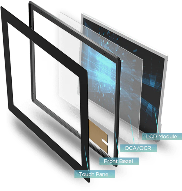
Bonding Technologies and Structural Integrity
The method by which the touch panel or protective cover lens is attached to the LCD cell significantly impacts both optical performance and mechanical durability.
Air Bonding vs. Optical Bonding
Air bonding (or frame bonding) involves using a perimeter adhesive to create a seal, leaving an air gap between the layers. This method is cost-effective and easy to repair but introduces two additional reflective surfaces (glass-to-air and air-to-LCD), which reduces light transmission to approximately 75%.
Optical bonding (or full lamination) fills this gap with an Optically Clear Adhesive (OCA) or liquid resin (OCR/LOCA) that has a refractive index matched to glass. This creates a single solid optical block, eliminating internal reflections and improving light transmission to over 90%.
| Feature | Air Bonding | Optical Bonding |
| Reflectance | ~13.5% | <0.2% |
| Sunlight Readability | Poor | Excellent |
| Impact Resistance | Moderate | High (Adhesive acts as shock absorber) |
| Condensation/Dust | Susceptible to fogging | Fully sealed; zero fogging |
| Touch Precision | Parallax error visible | No parallax; “pen-on-paper” feel |
For industrial IoT devices and medical equipment that must be sanitized frequently or operate in humid, dusty environments, optical bonding is the superior engineering choice. It prevents moisture ingress and enhances the structural strength of the entire assembly, distributing impact forces across the panel surface rather than concentrating them on the glass edges.
Display Interfaces: Performance Ceilings and Resource Constraints
The selection of a display interface is a critical trade-off between bandwidth, pin count, cost, and host processor compatibility.
Parallel Interfaces: MCU (8080/6800) and RGB (TTL)
Parallel interfaces transmit data across multiple lines simultaneously, making them straightforward to implement but high in pin count.
- MCU Interface: Also known as the CPU or 8080 interface, this relies on an internal Graphics RAM (GRAM) within the display’s driver IC. The host processor writes image data to the GRAM in bursts. This “smart” display architecture is highly efficient for microcontrollers (MCUs) like the STM32F1 series, as it eliminates the need for the processor to continuously refresh the display.
- Parallel RGB Interface: This interface sends raw pixel data directly to the display timing controller (TCON) in real-time. It requires dedicated signals for synchronization: Horizontal Sync (HSYNC), Vertical Sync (VSYNC), Data Enable (DE), and a Pixel Clock (PCLK). Because RGB panels usually lack internal GRAM, the host must stream data continuously at 60Hz, placing a significant load on memory bandwidth.
Serial and Differential Signaling: SPI, MIPI, and LVDS
Serial interfaces prioritize low wire counts and high-speed data transmission through advanced signaling techniques.
- Serial Peripheral Interface (SPI): Utilizing only 3 or 4 signal lines, SPI is ideal for compact IoT devices and small screens (under 3.5 inches). However, it is limited by bandwidth. At a 20MHz clock, an SPI bus can only drive a 320×240 display at approximately 16 frames per second (FPS), leading to visible stuttering during animations.
- MIPI DSI (Mobile Industry Processor Interface): The dominant interface for mobile and high-resolution compact devices, MIPI DSI utilizes 1 to 4 differential data lanes plus a clock lane. DSI v1.2 can support speeds up to 1.5 Gbps per lane, enabling it to drive 1080p @ 120Hz or 4K resolutions with minimal EMI. It supports two modes: Command Mode (for GRAM-enabled displays) and Video Mode (for real-time streaming).
- LVDS (Low-Voltage Differential Signaling): Designed for robustness, LVDS is the industrial and automotive standard for larger panels (7 to 20 inches). It uses low-swing differential signaling (~350mV) to transmit data over several meters with high noise immunity. Single-channel LVDS supports up to 1366×768, while dual-channel configurations (splitting data into odd and even pixel streams) are used for 1920×1080 (Full HD) panels.
| Interface | Effective Bandwidth | Pin Count | Typical Max Resolution | Key Benefit |
| SPI | < 80 Mbps | 4-6 | 320 x 240 | Low cost/complexity |
| MCU Parallel | 100-400 Mbps | 16-24 | 800 x 480 | Reduces MCU load |
| Parallel RGB | 500-2000 Mbps | 28-40 | 1024 x 600 | Low protocol overhead |
| MIPI DSI | Up to 10 Gbps | 4-18 | 4K+ | High-speed/Mobile |
| LVDS | Up to 10 Gbps | 8-25 | WUXGA+ | Noise immunity/Distance |
Data Bandwidth and Timing Calculations
Engineers must accurately calculate the system’s bandwidth requirements to ensure the selected host controller and interface can support the target resolution and frame rate without artifacts like tearing or flickering.
The Role of Blanking Intervals
A common mistake in display selection is calculating bandwidth simply as $Width \times Height \times Refresh Rate$. In reality, every display requires a “Blanking Interval” for internal synchronization and signal resetting between lines and frames. These intervals include:
- HSYNC/VSYNC Pulse Width: The time the sync signal remains active.
- Back Porch (HBP/VBP): The delay after a sync pulse before valid data begins.
- Front Porch (HFP/VFP): The delay after the last pixel before the next sync pulse.
Pixel Clock Frequency Calculation
The Pixel Clock (PCLK) represents the total number of clock cycles required to transmit a full frame, including blanking. The formula is:
$$PCLK = (H_{Active} + H_{Blanking}) \times (V_{Active} + V_{Blanking}) \times Refresh Rate$$
For a standard 800×480 (WVGA) panel refreshing at 60Hz:
- $H_{Active} = 800$
- $H_{Blanking} \approx 256$ (standard estimate)
- $V_{Active} = 480$
- $V_{Blanking} \approx 45$ (standard estimate)
- $PCLK = (1056) \times (525) \times 60 \approx 33.2 MHz$.
If using 24-bit True Color (RGB888), the required data throughput is:
$$Bandwidth = 33.2 MHz \times 24 bits \approx 796 Mbps$$
This calculation demonstrates why parallel RGB interfaces often encounter EMI issues above WVGA resolution, as driving 24 signal lines at these speeds creates significant electrical noise.
Electrical and Mechanical Reliability Specifications
Industrial custom TFTs must adhere to strict electrical and mechanical standards to ensure a multi-year service life in harsh conditions.
Power Management and Sequencing
A stable power supply is critical for preventing visual noise and long-term hardware failure. For a nominal 5.0V input, the voltage should be stable within ±0.25V, and ripple must be kept below 50mV.
Proper power sequencing is mandatory to avoid “latch-up” effects that can destroy the display’s driver IC. A typical sequence requires that IO Power (VDDI) is enabled before or simultaneously with the analog rails (VDD), followed by positive and negative gate voltages (VGH/VGL).
Ingress Protection (IP) and Sealing
The IP rating defines a device’s resistance to environmental contaminants.
- IP67: Dust-tight and resistant to immersion in water up to 1 meter for 30 minutes.
- IP68: Continuous immersion beyond 1 meter.
- IP69K: Protection against close-range, high-pressure, high-temperature water jets (100 bar at 80°C), essential for food processing and agriculture equipment.
MIL-STD-810H Reliability Standards
MIL-STD-810H is the global benchmark for testing durability under extreme environmental stress. Rather than a fixed certification, it is a framework where manufacturers tailor tests to the product’s use case.
| Test Method | Category | Operational Impact |
| Method 501.7 | High Temperature | Ensures performance in 71°C sun-baked vehicles |
| Method 502.7 | Low Temperature | Boot reliability in -33°C arctic environments |
| Method 503.7 | Temperature Shock | Prevents glass cracking during rapid shifts (-40 to 71°C) |
| Method 514.8 | Vibration | Simulates thousands of hours of heavy machinery juddering |
| Method 516.8 | Mechanical Shock | Validates unit survival after a 1.2-meter drop onto concrete |
Integration with Advanced Host Controllers
Integrating a custom TFT requires selecting a host processor that can handle both the graphical processing load and the physical interface requirements.
STM32 LTDC and MIPI Integration
STMicroelectronics’ STM32 series remains a popular choice for industrial HMIs. High-performance models like the STM32F429, F7, and H7 series feature an embedded LCD-TFT Display Controller (LTDC) that autonomously fetches pixel data from internal or external memory (SDRAM) to refresh the panel without CPU intervention.
For MIPI DSI displays, the STM32H7 series provides a DSI Host that encapsulates data into high-speed differential packets. Engineers must ensure that the number of data lanes on the display matches the host. While a 2-lane host can theoretically drive a 4-lane display, this is often limited by the display’s driver IC and will result in a lower maximum frame rate.
NXP i.MX 8 and Application Processors
For applications requiring high-performance 3D graphics or Edge AI, Linux-based application processors like the NXP i.MX 8 family are utilized. These processors support advanced MIPI DSI-2 and LVDS links, enabling smooth 4K video playback and multiple display coordination. Integration typically involves configuring a Board Support Package (BSP) and creating custom device tree overlays (.dts) to define display timings, power GPIOs, and backlight PWM frequencies.
Edge AI and the Future of HMI in 2026
The trajectory for 2026 points toward display modules becoming active participants in system intelligence. “Edge AI” and “Small Language Models” (SLMs) are moving inferencing from the cloud to the device, localized at the HMI.
Autonomous Industrial Intelligence
Modern industrial touch panels are transitioning from passive output devices to “active decoders”. Integrated with AI-powered vision systems, these panels can:
- Monitor Safety: Verify that operators are wearing required Personal Protective Equipment (PPE) before allowing a machine to start.
- Biometric Access: Use facial recognition to grant secure, tiered access levels instantly, replacing legacy physical ID cards.
- Predictive Maintenance: Analyze real-time machine data patterns to predict failures before they occur, visualizing results through advanced UI libraries like LVGL or Qt.
Multi-Modal Interaction
In environments where physical touch is difficult—such as surgeons wearing gloves or industrial operators in hazardous zones—the 2026 HMI integrates Natural Language Processing (NLP) for voice commands and gesture recognition sensors directly into the display module.
Sustainable Manufacturing and Circular Economy Regulations
Global supply chains are increasingly governed by sustainability mandates that directly influence display design and sourcing in 2026.
Regulatory Frameworks
Display manufacturers serving global markets must now comply with a suite of new regulations, particularly in the EU and North America:
- Ecodesign for Sustainable Products Regulation (ESPR): Mandates that circularity is designed into the product from the beginning, focusing on durability and the ease of component replacement.
- Digital Product Passports (DPPs): By mid-2026, manufacturers must provide structured digital data on material composition, recycled content, and carbon footprint for every module entering the European market.
- Circular Economy Act: Aims to establish a robust market for secondary raw materials, aiming to double Europe’s circularity rate by 2030.
Engineering Strategies for Sustainability
To align with these trends, product designers are moving away from permanent bonding where possible and adopting modular architectures:
- Design for Disassembly: Utilizing fasteners instead of strong chemical bonds to allow for backlight replacement or glass repair, significantly reducing the Total Cost of Ownership (TCO).
- Material Innovation: Replacing high-impact plastics with bio-based materials and utilizing lead-free manufacturing processes beyond standard RoHS compliance.
- Energy Efficiency: Integrating wide-bandgap semiconductors like Gallium Nitride (GaN) and Silicon Carbide (SiC) in power management units to reduce thermal waste and extend battery life in handheld terminals.
Step-by-Step Selection Framework
Navigating the custom TFT landscape requires a structured technical evaluation to avoid costly late-stage redesigns.
Step 1: Bandwidth and Processor Profiling
Calculate the required PCLK and data bandwidth using the formulas established in Section V. Cross-reference this with the host controller’s datasheet to ensure it can support the target resolution without exceeding the memory bus capacity.
Step 2: Environmental Stress Mapping
Define the maximum and minimum operating temperatures, potential for direct sunlight exposure, and likelihood of mechanical shocks. Choose the panel alignment (IPS for angles) and bonding method (Optical for outdoor) accordingly.
Step 3: Resource Constraint Analysis
Assess the PCB board space and the available IO pins. For space-constrained wearables, prioritize MIPI DSI or SPI. For large industrial PCs where routing is less of a concern, LVDS or Parallel RGB may offer better cost-to-performance.
Step 4: Lifecycle and supply Longevity
For industrial and medical sectors, prioritize chipsets and panels with a minimum of 5 years of guaranteed supply. Verify the manufacturer’s End-of-Life (EOL) notification policy, which should ideally be 6 to 12 months with a “Last-time Buy” opportunity.
Step 5: Compliance and Documentation
Ensure the module is ready for 2026 regulatory standards. Request the full test reports for MIL-STD-810H and IP ratings, and confirm the availability of material data for the Digital Product Passport.
Case Study: The 6.9-inch Custom Stretched Bar LCD (RV069LFM-350-40)
A prime example of 2026 customization is the rise of stretched “bar” type displays, designed for irregular spaces where traditional 4:3 or 16:9 aspect ratios are inapplicable.
The RV069LFM-350-40 is an innovative 6.9-inch panel with a 280 x 1424 resolution, utilizing a 40-pin MIPI interface. This module is designed for narrow installations, such as digital signage or control panels for high-end home appliances like refrigerators and ovens.
| Technical Parameter | Metric | Design Implication |
| LCD Active Area | 33.60 x 170.88 mm | Enables ultra-slim, narrow-bezel chassis |
| Display Mode | Normally Black (IPS) | All-direction viewing without color shift |
| Interface | 4-Lane MIPI DSI | Supports complex UI animations at 60Hz |
| Operating Temp | -20°C to +70°C | Suitable for industrial and appliance control |
| Driver IC | ST7703I | Modern controller with integrated gamma correction |
By pairing this unique bar-type display with a high-performance Android motherboard, manufacturers can create sleek, smartphone-like interfaces for security access points that support facial recognition and smooth scrolling in a form factor previously dominated by static LEDs.
Implementation Checklist for System Engineers
Successful display integration is the result of rigorous cross-disciplinary validation.
| Category | Verification Item | Engineering Target |
| Signal Integrity | Impedance Control | $100\Omega \pm 10\%$ for MIPI/LVDS |
| Signal Integrity | Length Matching | < 0.1mm intra-pair difference |
| Power | Sequencing | VDDI $\to$ VDD $\to$ VGH $\to$ VGL |
| Power | Ripple/Noise | < 50mV peak-to-peak |
| Optical | Viewing Angle | > 170/170 for IPS/VA panels |
| Mechanical | Bezel Alignment | ± 0.5mm mounting footprint tolerance |
| Firmware | VSYNC/TE Sync | Zero screen tearing in UI animations |
Conclusion and Strategic Outlook
As the industry advances toward 2027, the role of the custom TFT LCD has evolved from a simple visual output to the central intelligent hub of the embedded system. The successful implementation of these displays depends on an engineer’s ability to balance the physics of light transmission with the rigor of high-speed differential signaling and the necessity of environmental ruggedization. By following a data-driven selection framework—calculating bandwidth with precision, mapping environmental stressors to MIL-STD benchmarks, and designing for circularity and longevity—product teams can create resilient interfaces that define the next generation of industrial and commercial excellence.
The integration of Edge AI, the transition to sustainable material management, and the diversification of display form factors like stretched bar LCDs represent the new frontiers of HMI design. In this complex ecosystem, partnering with vertically integrated manufacturers who offer full-cycle innovation—from concept through certified manufacturing to lifecycle maintenance—is the primary strategic advantage for innovative global ventures.
FAQ: Frequently Asked Questions for Technical Buyers
What are the primary differences between “smart” and “dumb” display modules? “Smart” displays include an internal frame buffer (GRAM) within the driver IC, allowing the host to send commands or image data in bursts, which is common in SPI and MCU interfaces. “Dumb” displays (standard for RGB and MIPI Video Mode) lack internal memory and require the host to stream pixel data continuously, placing a higher demand on the processor’s memory bandwidth.
Why should I choose LVDS over MIPI DSI for an industrial project? While MIPI DSI is more power-efficient and common in compact mobile devices, LVDS is the preferred choice for industrial environments where the display and host are separated by more than 30 cm. LVDS offers superior noise immunity and can transmit reliable signals over cables up to several meters long.
How does optical bonding mitigate environmental failure in outdoor kiosks? Optical bonding eliminates the air gap where moisture can condense during temperature fluctuations (fogging). Additionally, the solid adhesive layer acts as a shock absorber, significantly increasing the panel’s resistance to vibration and mechanical impact, common in transportation and heavy machinery.
What is the significance of the “H” in MIL-STD-810H for 2026 products? Revision H is the latest update (2019) to the military testing standard, which introduces more realistic testing scenarios, such as temperature cycling simultaneously with vibration. It also provides clearer instructions for testing resistance to blowing sand, dust, and humidity, ensuring devices last longer in the field.
Can a processor with an RGB565 interface drive an RGB888 display? Yes, by using “high-bit alignment.” Connect the processor’s R0-R4 to the screen’s R3-R7 bits and ground the screen’s remaining low bits (R0-R2). This results in a reduction of color depth (from 16.7 million to 65,000 colors) and visible color banding in gradients, but maintains functional compatibility.
How will Digital Product Passports affect display sourcing in 2026? DPPs will require every display module to be accompanied by a digital record of its environmental impact, material origin, and reparability scores. Suppliers who cannot provide this data will face exclusion from the European market, making data transparency as important as technical performance for global OEMs.
What is the impact of power supply ripple on high-resolution TFTs? High ripple (exceeding 50mV) can cause visible noise, “crosstalk” between pixels, and flickering. In sensitive high-resolution panels, it can also interfere with the timing of differential signals, leading to intermittent link failures or data corruption in MIPI and LVDS streams.
Why is IPS technology preferred for floor-mounted industrial consoles? IPS (In-Plane Switching) provides a consistent image even when viewed from extreme angles. This is critical for consoles mounted below eye level, where a standard TN panel would appear washed out or inverted to an operator looking down at the screen.
How do I handle a mismatch between a 4-lane MIPI display and a 2-lane host? Compatibility depends entirely on the display’s driver IC. Some controllers are configurable via hardware pins or register settings to operate in 2-lane mode, while others are hardwired for 4 lanes. If the host only has 2 lanes and the display is fixed at 4, the connection will fail.
What are the key benefits of using SiC or GaN in display power circuits? These wide-bandgap semiconductors are more efficient than traditional silicon, allowing for smaller power units with lower heat generation. This enables thinner, fanless display designs that are more reliable in sealed, ruggedized enclosures.
What is the expected lifespan of a professional-grade TFT backlight? Most industrial-grade backlights are rated for 50,000 hours to “half-brightness.” High-brightness outdoor displays may have a shorter lifespan (20,000-30,000 hours) if operated continuously at maximum intensity without adequate thermal management.
How does In-Cell touch technology differ from standard PCAP? In-Cell technology integrates the touch sensors directly into the liquid crystal layers during the cell manufacturing process. This results in thinner, lighter displays with better optical clarity and lower assembly complexity compared to traditional add-on PCAP sensors.
What common errors lead to screen tearing in high-speed UIs? Tearing occurs when the memory update cycle of the processor is not synchronized with the display’s refresh rate. This is typically solved by using a Tearing Effect (TE) signal or a VSYNC interrupt to ensure that image data is only updated during the display’s vertical blanking interval.
Why is VA technology increasingly used in luxury automotive interiors? VA (Vertical Alignment) offers contrast ratios as high as 3000:1, providing deep, “true” blacks that consumer-grade IPS panels cannot match. This allows the display to blend into the black interior trim of a vehicle dashboard when the system is off, creating a seamless, high-end aesthetic.
Is it possible to use a standard HDMI source for a custom MIPI TFT? Yes, but a bridge chip (HDMI-to-MIPI) is required. This adds approximately 3.00 to 5.00 USD to the BOM cost and requires a complex PCB layout for the high-speed differential pairs.
What is the role of a “serializer/deserializer” (SerDes) in LVDS systems? SerDes chips take the wide parallel RGB bus from the host processor and condense it into high-speed serial differential pairs for transmission to the display. This reduces the number of wires needed across hinges or cables and improves electromagnetic compatibility (EMC).